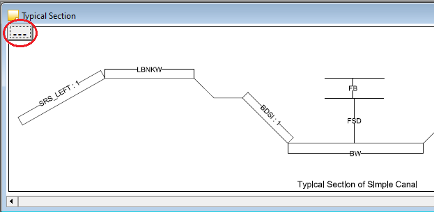
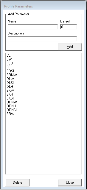
Select the newly created DB from the Profiles list. Now go to Profile>>Profile Points menu option. This will bring up the profile editor. Before you start creating your profile, it helps to have a typical section handy. You can create your parameters quickly looking at the typical section.

In case you are wondering how to change the typical section image shown alongside the Design Profile Values, just click on the (…) button on the left top most corner of the image and select a GIF file of your choice.

Some parameters are default in the application as mentioned below
DEFAULT Parameters
- CL : Center Level; This is the design center level.
- LP_Off : Calculated offset of the previous point on the left side.
- RP_Off : Calculated offset of the previous point on the right side.
- LP_Val : Calculated design level of the previous point on the left side.
- RP_Val : Calculated design level of the previous point on the right side.
There are two more default parameters which are automatically entered and used by the software. The final toe points for the closing slope need not be entered by the user but the software takes care of it. The user only needs to enter the values of SRS_Left and SRS_Right in the profile sheet as mentioned.
- SRS_Left : Left hand side toe slope made by design closing on the ground level.
- SRS_Right : Right hand side toe slope made by design closing on the ground level.
From the typical section, add the required parameters with name and default value. The name can be anything of your choice without space or special characters except for an underscore.

For example, if you want to design a simple canal, the parameters would typically be:
- BW : Bed Width
- BDSl : Bed Slope
- FSD : Full Supply Depth
- FB : Free Board
- LBKW : Left Bank Width
- RBKW : Right Bank Width
