LXQ CAD can plot your drawings to AutoCAD software. You need to fill the Design Levels and Initial Levels for this to work. Select the Output>>Plot L Section menu option.

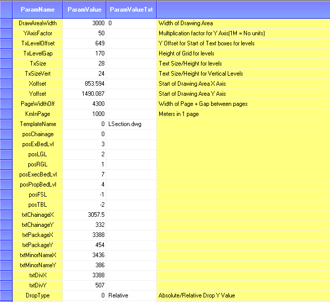
The L Section is plotted to AutoCAD using the L Section template file and drawing parameters found in the Tools>>Drawing Parameters menu option.

DrawAreaWidth: This is the total width of only the template area where the L Section lines are plotted. This value is in CAD units. This value combined with the KmInPage value determines the X axis scale of the drawing.
YAxisFactor: This determines the number of CAD units used to display 1 meter on the Y axis.
TxLevelOffset: Y axis value where level value text starts.
TxLevelGap: Distance on Y axis between level value texts.
Xoffset, Yoffset: Co-ordinates where the drawing area of the template starts.
PageWidthOffset: Total width of page including gap between consecutive pages.
KmInPage: longitudinal distance in meters to display in one page of L Section.
TemplateName: The filename of the template used to display the L Section for this profile. The templates are found in the Template folder in App Path. You can use your own drawing file as a template.
posChainage, posExBedLevel, posLGL, posRGL, posPropBedLevel: Position or order of level text values displayed on the L Section. The Y axis value for the text is determined by the following formula:
TxLevelOffset + posLGL x TxLevelGap
The value can be negative, in which case the text is displayed above TxLevelOffset.
txtChainageX, txtChainageY, txtPackageX, txtPackageY: These values specify the absolute co-ordinates on the template where the Package name, Section details and Chainage range are displayed at the bottom corner or top corner of the drawing.
All the above mentioned drawing parameters are already entered in the Profiles shipped with the software. You need not change them in most cases unless you are planning to use your own template file to draw the L Section.
