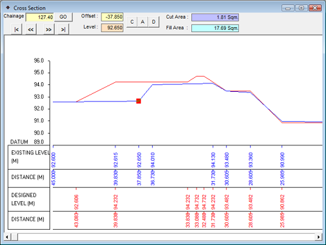
To view this section use the Output>>View X Section menu option. It brings up the following screen :

If you have filled Design levels, Design profile values and Initial levels correctly, then you can view the cross section for the current chainage. The chainage is indicated in the top portion of the form. The navigational buttons are provided alongside to move to the first chainage, previous chainage, next chainage and last chainage. If the entire section doesn’t fit on screen, you can use the scroll bar of the mouse or the horizontal scroll bar on the form. You can Change, Add or Delete the Initial levels for the current chainage. For doing this, move to the desired chainage using navigational buttons. Alternatively, you can also enter the chainage directly in the text box and press GO button.
Change: You can modify the offset and level of the currently selected point denoted by the red pointer on the screen. Click on C button on top of the form or press the ‘C’ key. You will be asked to enter the new Offset and Level. You can either enter it in the text boxes provided OR click on the location of the graph where you want the point placed and the system calculates the co-ordinates for you. Once you have finalized the point, click on Yes or press ‘Y’ key or ENTER key to confirm the operation. You can cancel the task by pressing ESC key or ‘N’ key or clicking on No.
Add: You can add a new point by clicking on A button on top of the form or pressing the ‘A’ key. You will be asked to enter Offset and Level. Enter the values in the text boxes provided OR click on the location of the graph where you want the new point placed. Click on Yes or press ‘Y’ key or ENTER key to confirm the operation. You have the option of cancelling the task by pressing ESC key or ‘N’ key or clicking on No.
Delete: You can delete the currently selected point by clicking on D button on top of the form or pressing the ‘D’ key. You will be asked for confirmation. Click Yes or press ‘Y’ key or ENTER key. Cancel the deletion by pressing ESC key or ‘N’ key or clicking on No.
Note: You modify the Initial Levels or Original Ground Levels(OGL) in the Cross Section. If you wish to modify the Design Levels, then view the Longitudinal Section.
The Cross Section is plotted using Design Levels and Design profile values. You must fill the design profile values to generate the Cross Section.
